HomeElectrical diagramsÇift Pompa Alternasyon (Duty/Standby)
Çift Pompa Alternasyon (Duty/Standby)
IEC 60617 compliant, hand-verified reference diagram — view it free, print it, or have the AI adapt it to your own project.
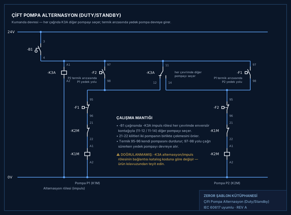
Circuit note
Kumanda devresi 24VDC. -B1 flatör/basınç çağrısı barayı besler; -K3A alternasyon (impuls) rölesi her çevrimde enversör kontağıyla (11-12/11-14) diğer pompayı seçer. Her pompa kolu: kendi termik NC (95-96) + karşı kontaktör NC kilidi (21-22) + bobin. Termik arızasında ilgili 97-98 NO yolu, çağrı sürerken yedek pompayı doğrudan baradan besleyerek devreye alır; 21-22 kilitleri iki pompanın birlikte çekmesini önler. DİKKAT: Alternasyon impuls rölesi bağlantısı katalog koduna göre değişir — DOĞRULANMAMIŞ, bağlantı ürün kılavuzundan teyit edilmeli. Güç bölgesi gerekmediğinden yalnız kumanda sayfası.
Ask the AI
Type this query in the app and the same diagram appears at once; add the motor rating and it also computes the contactor, overload, breaker and cable cross-section table.
Diagrams in the same category
- Dalgıç Pompa Kumandası (Flatörlü, Trifaze)
- Hidrofor Kumandası (Basınç Şalterli)
- Sıvı Seviye Rölesi ile Depo Dolum (Elektrotlu)
- Rezistanslı Isıtıcı Sıcaklık Kumandası
- Aspiratör / Fan Kumandası (EL-0-OTO)
- Solenoid Valf Kumandası (DC / AC)
- Kompresör Kumandası (Basınç Şalterli)
- Haftalık Zaman Saati ile Otomatik Çalıştırma
- Kademeli Üç Pompa (Hidrofor Grubu) Kumandası
- El-0-Oto Seçicili Motor/Pompa Kumandası
- 3 Faz Rezistans Isıtıcı: Termostat + Emniyet
- Çevrimsel Zamanlayıcı ve Flaşör Devresi