HomeElectrical diagramsVFD (Sürücü) Temel Bağlantı
VFD (Sürücü) Temel Bağlantı
IEC 60617 compliant, hand-verified reference diagram — view it free, print it, or have the AI adapt it to your own project.
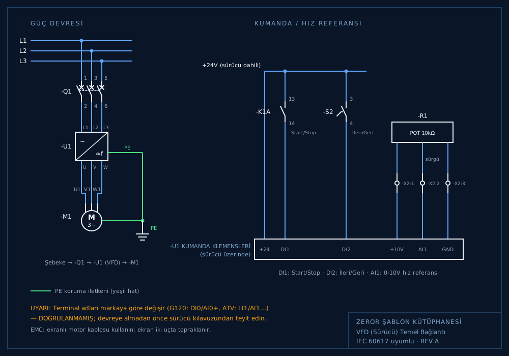
Circuit note
Güç: L1/L2/L3 → -Q1 (3 kutuplu kesici, 1-2/3-4/5-6) → -U1 VFD (giriş L1/L2/L3, çıkış U/V/W) → -M1 3~ motor (U1/V1/W1). PE hattı (yeşil #4ADE80) hem sürücü hem motor gövdesine, toprak sembolüne iner. Kumanda: sürücü dahili +24V → DI1 (-K1A NO 13-14, Start/Stop) ve DI2 (-S2 seçici 3-4, İleri/Geri); AI1 hız referansı: -R1 10kΩ potansiyometre, uçlar +10V/GND, sürgü → AI1 (-X2:1..3 klemensleri). UYARI: terminal adları markaya göre değişir (G120: DI0/AI0+, ATV: LI1/AI1 vb.) — DOĞRULANMAMIŞ, sürücü kılavuzundan teyit şart. EMC: ekranlı motor kablosu, ekran iki uçta topraklanır. DI COM (dijital giriş ortak ucu) sürücü tipine göre +24V veya 0V’a köprülenir (PNP/NPN seçimi) — kılavuzdan teyit edin.
Ask the AI
Type this query in the app and the same diagram appears at once; add the motor rating and it also computes the contactor, overload, breaker and cable cross-section table.